IntroductionA unique feature of the GX3500 FPGA card is that it can accommodate an expansion card assembly that can be used to customize the interface to the UUT. This eliminates cumbersome and physically difficult to integrate external boards from the test system.
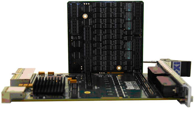
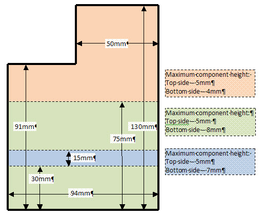
The custom expansion interface is contained on a mezzanine board that sits piggyback on the GX3500 FPGA PCB (figure 1). The expansion board provides approximately 105 cm2 on each the front and back sides (figure 2), and obtains power from the GX3500.
  Figure 1: GX3500 with Expansion Board Figure 1: GX3500 with Expansion Board
 Figure 2: GX3500 Expansion Board Design Area Figure 2: GX3500 Expansion Board Design Area
Software controlled relays control whether the 160 FPGA signals are routed directly to the GX3500 front panel connectors, or whether the I/O signals are intercepted from the FPGA and routed through the expansion board. The relays can be controlled using the API function GxFpgaSetExpansionBoardBypass(), or using the GX3500 Soft Panel (figure 3).
 Figure 3: Expansion Board Bypass Control Figure 3: Expansion Board Bypass Control
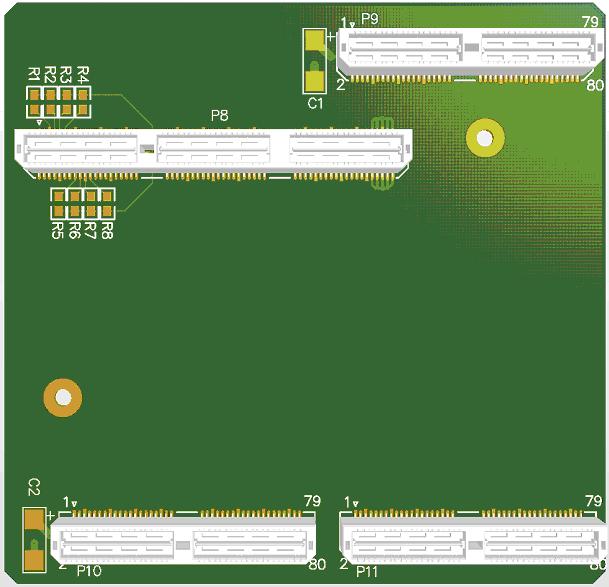
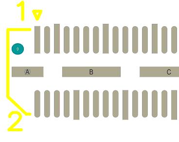
High Speed Terminal Strips, manufactured by Samtec, are use to provide power to the expansion board, and bring the signals on and off the board (figure 4). The middle bar of the connector is used for ground and power connections to the expansion board, while the outer pins provide access to the I/O signals (figure 5).
 Figure 4: Expansion Connectors Figure 4: Expansion Connectors
 Figure 5: Power Connections Figure 5: Power Connections
Design GuidelinesWhen designing an expansion interface for the GX3500, consideration must be given to the following:
- Board Area: Maximum board surface area is about 200 cm2.
- Component Height: Maximum component height is 8mm, with some areas on the board reduced to a maximum component height of 5mm.
- Power Requirements: The GX3500 expansion connectors provide multiple power voltages to the expansion board. Provide adequate decoupling and filter capacitors and do not exceed the maximum power budget for the voltages:
- Cooling: Make certain the air flow is not blocked to higher power components.
- Termination: Provide proper trace impedance and, if necessary, termination for high-speed signals and signals with fast edge rates.
A full GX3500 Expansion Board Design Guide is included in the GX3500 User Guide.
|