Introduction: The GX1110 is a 100 MHz, single-channel PXI Arbitrary Waveform Generator (AWG) that can also operate as a function generator with Direct Digital Synthesis (DDS) of the clocking resource. Built-in waveforms are available for use with both the DDS or AWG modes of operation and include Sine, Triangle, Ramp, Noise, Gaussian pulse and Sinx/x.
The GX1110 can apply either Amplitude Modulation (AM) or Frequency Modulation (FM) to the carrier waveform using either an internal modulation source or an external modulation signal.
This article demonstrates how to program the GX1110 to generate AM and FM signals using an internal modulation source. The modulating signal has three parameters that define its characteristics.
For AM, those parameters are the modulation frequency, the modulation amplitude and the modulation waveform.
For FM, the parameters are modulation frequency, deviation and modulation waveform. | |
Specifications for the modulation parameters are:
Modulation Parameters:
Source: Internal or External
Frequency: 0 Hz - 20 KHz
AM Amplitude: 0% - 100%
FM Deviation: 0% - 100%
Waveform: Sine, Square, Triangle, Ramp Up, Ramp Down, Noise
Program Examples: The following ‘C’ code sets the GX1110 to generate a
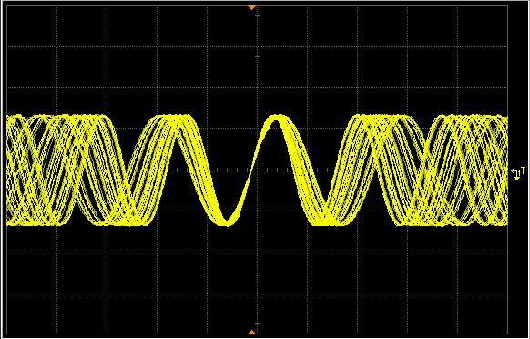
100.0 KHz carrier signal with a 5.0V amplitude, and defines the modulation to be FM, 16.0 KHz modulation frequency and a 20.0 KHz frequency deviation. The resulting waveform is shown in figure 1.
// Initialize the GX1110 in slot #6
GtWaveInitialize(6,&nHandle,&nStatus);
// Reset the GX1110
GtWaveReset(nHandle,&nStatus);
// Set the GX1110 to Function Generator mode
GtWaveSetOperationMode(nHandle,GTWAVE_OPERATING_MODE_FUNC,&nStatus);
// Set output to 5.0V, Enabled, Sine Wave, 100.0 KHz Frequency
GtWaveSetAmplitude(nHandle,GTWAVE_CHANNEL_A,5.0,&nStatus);
GtWaveSetOutputState(nHandle,GTWAVE_CHANNEL_A,True,&nStatus);
GtWaveFuncSetWaveform(nHandle,GTWAVE_CHANNEL_A,GTWAVE_WAVEFORM_SINE,&nStatus);
GtWaveFuncSetFrequency(nHandle,GTWAVE_CHANNEL_A,1.0E5,&nStatus);
// Set FM modulation source to internal
GtWaveFuncGetFmSource(nHandle,GTWAVE_CHANNEL_A,GTWAVE_FUNC_FM_SOURCE_INTERNAL, &nStatus)
// Set modulation to FM Sine Wave, 16 KHz Modulation, 20.0 KHz Deviation
GtWaveFuncSetFmWaveform(nHandle,GTWAVE_CHANNEL_A,GTWAVE_WAVEFORM_SINE,&nStatus);
GtWaveFuncSetFmFrequency(nHandle,GTWAVE_CHANNEL_A,16.0E3,&nStatus);
GtWaveFuncSetFmDeviation(nHandle,GTWAVE_CHANNEL_A,20.0E3,&nStatus);
// Enable FM modulation
GtWaveFuncSetFmState(nHandle,GTWAVE_CHANNEL_A,True,&nStatus);
// Set the GX1110 to Run state
GtWaveRun(nHandle,GTWAVE_CHANNEL_A,&nStatus);

Figure 1: Frequency Modulation Waveform
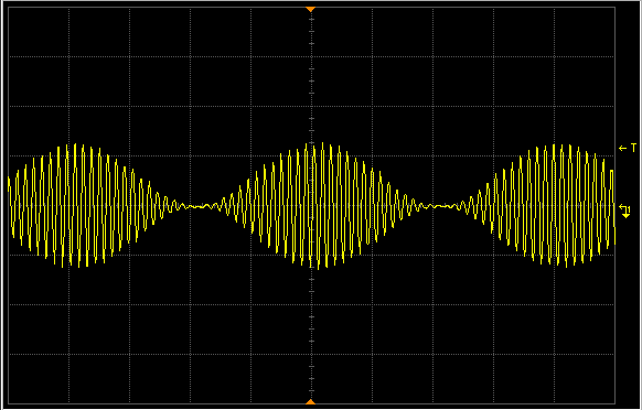
The following ‘C’ code sets the GX1110 to generate a 1.4 KHz carrier signal with a 5.0V amplitude, and defines the modulation to be AM, 50.0 Hz modulation frequency and 100% modulation level. The resulting waveform is shown in figure 2.
// Initialize the GX1110 in slot #6
GtWaveInitialize(6,&nHandle,&nStatus);
// Reset the GX1110
GtWaveReset(nHandle,&nStatus);
// Set the GX1110 to Function Generator mode
GtWaveSetOperationMode(nHandle,GTWAVE_OPERATING_MODE_FUNC,&nStatus);
// Set output to 5.0V, Enabled, Sine Wave, 1.4 KHz Frequency
GtWaveSetAmplitude(nHandle,GTWAVE_CHANNEL_A,5.0,&nStatus);
GtWaveSetOutputState(nHandle,GTWAVE_CHANNEL_A,True,&nStatus);
GtWaveFuncSetWaveform(nHandle,GTWAVE_CHANNEL_A,GTWAVE_WAVEFORM_SINE,&nStatus);
GtWaveFuncSetFrequency(nHandle,GTWAVE_CHANNEL_A, 1.4E3,&nStatus);
// Set modulation to AM Sine Wave, 50 Hz Modulation, 100% Amplitude
GtWaveFuncSetFmWaveform(nHandle,GTWAVE_CHANNEL_A,GTWAVE_WAVEFORM_SINE,&nStatus);
GtWaveFuncSetFmFrequency(nHandle,GTWAVE_CHANNEL_A,50,&nStatus);
GtWaveFuncSetFmDeviation(nHandle,GTWAVE_CHANNEL_A,20.0E3,&nStatus);
// Enable FM modulation
GtWaveFuncSetFmState(nHandle,GTWAVE_CHANNEL_A,True,&nStatus);
// Set the GX1110 to Run state
GtWaveRun(nHandle,GTWAVE_CHANNEL_A,&nStatus);

Figure 2: Amplitude Modulation Waveform
Figure 2: Amplitude Modulation Waveform
Figure 2: Amplitude Modulation Waveform