OverviewOften, testing devices with digital interfaces requires the ability to wait for the device to respond to specific pattern sequences sent to it. This is especially true for devices that incorporate bus transfers that use hardware handshaking to synchronize the data transfer. The GX5280/GX5290 digital instruments family of cards provide sixteen external event inputs that can be used in support of this handshaking process. This article explains how to use the external events to perform synchronous Pause/Resume operations with the device under test (DUT).
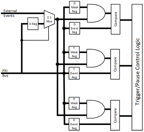
External EventsThe GX5280 and GX5290 digital IO instruments (DIO) provide sixteen external input signals that can be used to pause and trigger (resume) the digital pattern sequences. This ability to pause, and then resume pattern sequencing based on hardware signaling is essential for performing closed-loop handshaking of data transfers. Figure 1 below provides a functional block diagram of the external event control.
|
|
 Figure 1 - External Events Block Diagram Figure 1 - External Events Block Diagram
There are three pairs of registers that define how the external events can be used, labeled as the 'D' event', the 'T' event and the 'P' event. Each register pair has a sixteen bit event pattern, and a sixteen bit event mask for ignoring unused bits - where a logic '1' enables an event input signal, and a logic '0' disables, or masks, the corresponding input. Together, the event/mask combination defines a sixteen bit value that is passed to the pattern sequencer for evaluation.
The 'D' and 'T' events are used to trigger the pattern sequencer. Triggers can be based on a single pattern match of the 'D' or 'T' event, or can be used in combination to define a trigger sequence that must be met in order to qualify as a valid trigger - as in a pre-trigger followed by the actual trigger. The event order can be defined either as 'D' followed by 'T', or 'T' followed by 'D'.
The 'P' event will force the DIO sequencer to pause pattern execution when the defined event condition is met.
The DIOs do provide software commands that can pause and trigger pattern sequencing, but software control is not synchronized to the data flow, and typically cannot operate at speeds the DUT is capable of, or data transfer protocols require. Control registers built into the instrument pattern sequencer can be used to pause execution at a specific vector, but the control register is only one state deep - meaning that without software intervention, only one pause command can exist in the entire pattern sequence. Reprogramming the pause vector using software can be used to extend the one-shot pause command, but slows the handshaking process to what might be unacceptable timing.
Note: The GX5295 only provides eight external event inputs. Otherwise, the functionality described in this article applies to the GX5295. The GX5296 and GX5960 series instruments use a completely different architecture and are not covered in this article.
At-Speed Hardware HandshakingUtilizing the external event inputs and unused IO pins on the DIO, at-speed hardware handshaking can be achieved. By connecting unused pin(s) from the J1 connector to the external event inputs on the J3 connector, you can program a hardware "pause" at virtually any vector, or any number of vectors in the full pattern length of the instrument - effectively turning the unused IO channels into additional pause commands. For example, if IO channel 30 (J1-P31) is connected to external event input signal 2 (J3-P3), then IO channel 30 becomes the pause control signal if the 'P' event is defined as Mask=0x0004, and Event=0x0004. Then any vector where IO channel 30 is programmed to a logic '1' will force the DIO into a paused state. Assuming the DIO is acting as the controller in a data transfer involving handshaking, programming a 'P' event at the vector(s) where the controller must wait for the DUT to acknowledge the data transfer forces the entire DIO domain (all IO channels) into a Paused-Waiting-For-Trigger state. Continue triggers can be generated via software, come from the external trigger input, be received from the PXI backplane, or come from using the same external events used to force the pause state.
If the DUT handshake response is also connected to external event inputs, say event signal 0 (J3-P1), and you elected to use the 'D" event to resume pattern sequencing, then you would define the 'D' event trigger as Mask=0x0001, and Event -0x0001. When the DIO is paused, a logic '1' on event input 0 will trigger the instrument and continue pattern execution.
What's The Catch?There are some caveats to using external events:- Events are level sensitive, and are not generated by rising or falling edges
- The pause is not immediate. It takes a minimum of 16 vectors to effect a pause. The maximum run-on depends on the pattern rate. Reasons for variations in the vector run-on are described below:
- There is an approximately 350 nS propagation delay for pause events to be available to the pattern sequencing logic.
- There is a 16-state stimulus/response pipeline that must be considered when using DIO loop-back for pause control.
- Synchronous External Event Pause/Trig requires only 1 vector to initiate the pause.
- Asynchronous External Event Pause/Trig requires a minimum of 2 vectors to initiate the pause.
- A maximum of 8 vectors can be used for initiating a pause. The DIO pipeline will retain pause event states which could initiate a pause immediately after a continue trigger is received if the pause signal is applied across too many vectors.
- At high data rates, ground bounce can cause false or intermittent Pause/Trigger operations as the bounce could exceed the vector period the instrument is running at.
The approximate 350 nS propagation delay and 16-state pipeline will delay pausing the DIO pattern from a minimum of 16, to a maximum of approximately 50 vector states. The patterns immediately following the pause signal should be programmed with static states so as not to vary the logic states presented to the DUT while waiting for the handshake acknowledge. The length of the run-on depends on the data rate of the DIO, for reason explained below.
 Figure 2 - Low Data Rate Pause Timing Figure 2 - Low Data Rate Pause Timing
In Figure 2 above and Figure 3 below, the propagation delay (Tpd) is the same duration (~350 ns). Figure 3 has been stretched to better show the timing detail. You can see in Figure 2 that Tpd is less than 1 vector period, so its effect is contained in the first clock cycle after the pause signal. The pattern clock is slow enough that the effect of Tpd is hidden (contained) in the vector where the pause trigger is generated (blue clock cycle). So the pause run-on is affected only by the instrument pipeline, and the DIO pauses at 16 vectors after the pause event (red clock cycle).
 Figure 3 - High Data Rate Pause Timing Figure 3 - High Data Rate Pause Timing
In Figure 3, the vector clock is running much faster, and the same Tpd duration extends across multiple pattern clocks. During Tpd, pattern clocks (yellow clock cycles) have no effect in moving the pause trigger state through the instrument pipeline. So, in effect, the pause run-on is extended by the number of pattern clocks contained in the duration of Tpd - five clock cycles in the example. The vector in which the pause occurs is 21 vectors after the pause event (red clock cycle) - 16 vectors for the pipeline + 5 vectors for Tpd. If the DIO is running at 100 MHz (10 nS) period, an additional 35 clocks could occur during Tpd (350 nS / 10 nS period) - give or take. At high data rates, and due to minor variations in Tpd delays, there is some ambiguity concerning the exact vector where the pause will take effect, so the pipeline and Tpd run-on should be characterized for the data rate at which the test pattern will be run.
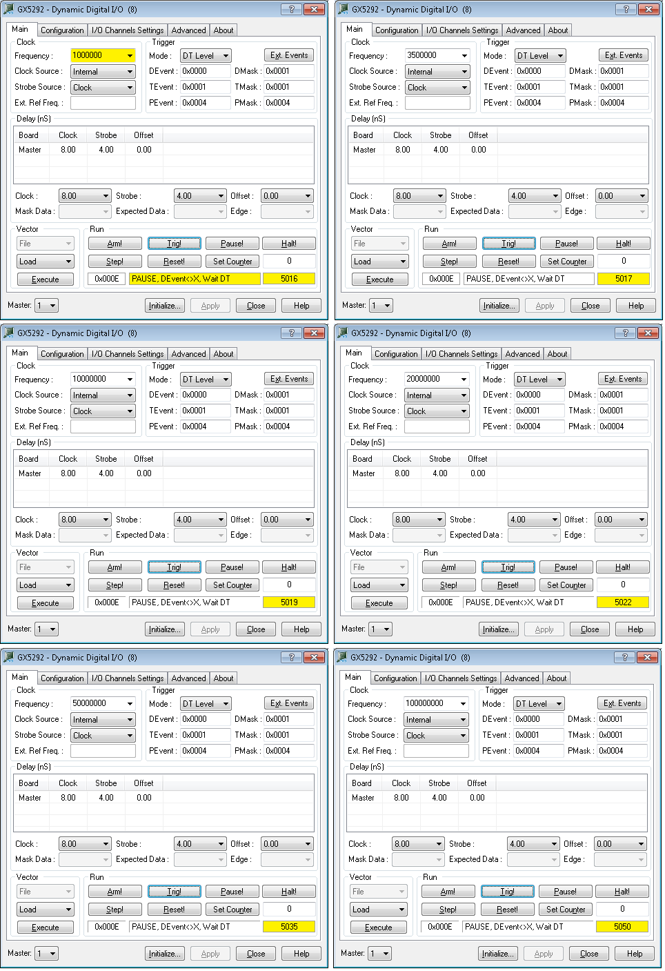
Examples of this are shown in Figure 4:1 - 4:6 below. Each image is a screen capture of the GtDio panel running the same test pattern. In each case, the pause signal was programmed at vector 5000. The only difference between the screen captures is the data rate at which the pattern was executed. Reviewing the highlighted fields of Figure 4:1 shows the pattern clock is running at 1 MHz. The period, 1 uS, is well above the Tpd value, so the pause takes effect at vector 5016. Subsequent figures show different pattern clocks, up to 100 MHz, and the resulting pause vector for each.
 Figure 4 - Pause Vector at 1 MHz - 100MHz Data Rate Figure 4 - Pause Vector at 1 MHz - 100MHz Data Rate
ConclusionWhile the GX5280 and GX5290 Digital IO instruments provide pattern control using programmable registers and/or software commands, utilizing unused DIO resources can extend the functionality of the DIO instruments to support multiple pause/resume points across the entire depth of the UUT test pattern, or within multiple pattern sets that can be pre-loaded into the 64M vector DIO pattern memory. | |
.
|