One of the capabilities that differentiate a test and measurement instrument installed in a PXI chassis from traditional rack-and-stack instruments and instruments installed in a PCI mainframe, is the addition of the PXI trigger bus. This bus facilitates a more tightly integrates suite of instrument by allowing PXI-based instruments to synchronize operation using common clocks and triggers, without the need for external wires or cables. However, due to the nature of the PCI bus, and by extension, the PXI bus, bridges are required to link bus segments together when more than 8 devices are installed on the bus. The PCI bridge extends the computer data bus, but does nothing about extending the PXI trigger bus across multiple bus segments, which is necessary to maintain the synchronization capabilities designed into the PXI bus across the full backplane.
Early introductions of PXI chassis' accommodated extending the PXI trigger bus by using jumpers on the chassis backplane to enable triggers and set the direction control of the trigger signals between bus segments. If for any reason the trigger bus ever needed to be reconfigured, the chassis would have to be powered down, instruments removed to gain access to the backplane jumpers, and the jumpers manually reconfigured to accommodate the new triggering requirements. This dated technique is still used by many PXI chassis’.
With the introduction the Smart Chassis series from Geotest, this dated methodology has been replaced with software control for mapping and enabling PXI triggers across bus segments. Trigger mapping can now be set using software commands or virtual instrument panels, all while the chassis is powered on and instruments installed. Geotest chassis’ that include this “Smart” feature are the GX7000A, GX7100A, GX7300 and GX7600.
To configure trigger mapping you must have the appropriate chassis DLL driver installed and be connected to the chassis using either an embedded controller or a PXI bus extender connected to an external host PC. To manually set the trigger direction, launch the Chassis Panel application by selecting GxChassis Panel on your desktop or from the Windows Start Menu. Click on the Initialize button and follow the directions for initializing the chassis (figure 1).
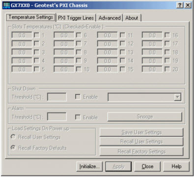 Figure 1 - Generic GX7XXX Chassis Panel Figure 1 - Generic GX7XXX Chassis Panel
From the main panel select the PXI Trigger Lines tab. The PXI Trigger Lines tab will reflect the number of slots available on the chassis being controlled. The GX7000A and GX7300 each have twenty (20) slots (figures 2 and 3, respectively), the GX7100A has fourteen (14) slots (figure 4) and the GX7600 has nine (9) slots (figure 5).
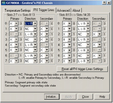 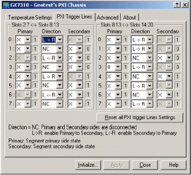 Figure 2 - GX7000 Chassis Triggers Tab Figure 3 - GX7300 Chassis Triggers Tab Figure 2 - GX7000 Chassis Triggers Tab Figure 3 - GX7300 Chassis Triggers Tab
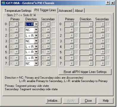 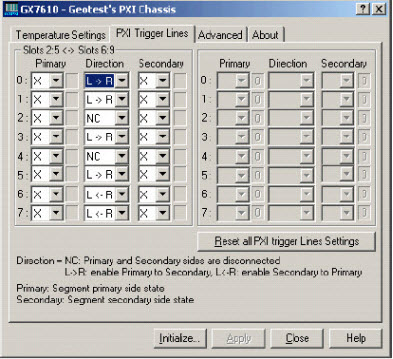 Figure 4 - GX7100 Chassis Triggers Tab Figure 5 - GX7600 Chassis Triggers Tab Figure 4 - GX7100 Chassis Triggers Tab Figure 5 - GX7600 Chassis Triggers Tab
The screen indicates which slots are the primary slots and which slots are the secondary slots associated with each bridge. The chassis will continuously monitor the state of the triggers on all of the bus segments and report them via the panel as either a logic "0" or a logic "1". Each bridge between bus segments provides three controls for each trigger line. Simply click on the desired control and a drop-down list will be presented that allows you to select the appropriate parameter:
Direction Control - Direction of the trigger mapping:- NC Trigger Mapping Disabled)
- L -> R Primary to Secondary Mapping
- L <- R Secondary to Primary Mapping
Primary Control / Secondary Control - Define whether the trigger is passive (monitored only) or actively driven by the chassis:- X Monitor only, driven by instruments installed on that bus segment
- 0 Force trigger line to logic "0"
- 1 Force trigger line to logic "1"
- blank Monitor only, mapped to (driven by) the opposite bus segment
Once all of the triggers have been mapped for each bridge, the settings can be saved to EEPROM by selecting the Temperature Settings tab and clicking on the Save User Settings button, as represented by the GX7300 panel in figure 6. Once saved, the user defined PXI trigger mapping can be restored manually by clicking on the Recall User Setting button on the Temperature Setting tab, or automatically on power-up by clicking on the Recall User Settings radio button under the Load Settings On Power Up control group. Be sure to save user settings each time you change the Load Settings On Power Up control or the new selection will not be remembered during the next power cycle.
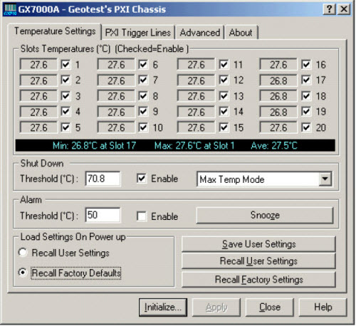 Figure 6 - Save/Recall User Settings Figure 6 - Save/Recall User Settings
Setting of the PXI bridge trigger mapping can also be accomplished programmatically using the GxChassisSetPxiTriggerLine function, and the GxChassisGetPxiTriggerLine function can be used to query the current trigger mapping settings . The format for these functions are described fully in the GX7XXX User Guide:
GxChassisSetPxiTriggerLine (nHandle, nLine, nSegment, ucDirection, nPrimaryMode, nSecondaryMode,pnStatus)
GxChassisGetPxiTriggerLine (nHandle, nLine, nSegment, pucDirection, pnPrimaryMode, pnSecondaryMode,pnStatus)
The Load Settings On Power Up parameter can be set programmatically using the GxChassisRecallSettings function. The format for this function is described fully in the GX7XXX User Guide:
GxChassisRecallSettings (nHandle, nSettingSource, pnStatus)
|