IntroductionThe switching employed in Automated Test Equipment (ATE) can be as complex as any other component of a test system. The ultimate specifications of the test system directly depend on the integrity of the switching used. In order to design an ATE system the designer must understand the best components to design a switching system capable to perform the required tests. The following article describes typical switching components used in today's modern test systems. For more information about PXI products, services and support options visit our web site at http://www.marvintest.com
Basic Test SystemTo test a device, component, or subassembly effectively, a test system must set up prescribed input conditions and monitor its responses. Testing generally means applying a stimulus to a unit under test and checking the response, as shown in Figure 1:
 Figure 1: A Simple Test System Figure 1: A Simple Test System
Almost all stimulus and response signals are electrical, but they could be non-electrical, such as heat, light, or motion. Non-electrical signals are usually converted to, or from, electrical signals to permit computer control or data analysis. Electrical signals are measured, or sourced, by the following common test instruments:
- Measure - Oscilloscope, voltmeter, frequency counter, spectrum analyzer, waveform analyzer
- Source - Power supply, current source, pattern generator, pulse generator, frequency synthesizer
- Source/Measure - Ohmmeter, capacitance meter, network analyzer, signature analyzer
Measure and source functions can be combined in the same instrument and even in the same leads, for example, an Ohmmeter that measures voltage and source current on two leads. In basic test systems, the source and measure instruments are connected to the unit under test (UUT) by direct interface wiring. A better test system makes these connections via switching. The purpose of employing a switching system is to:
- Test several UUTs during one test session
- Test multiple points on a UUT
- Connect many measure or source instruments
The various configurations are shown in Figures 2 - 4. These basic configurations may be combined to form systems that are more complex. In most systems, it is best to measure the output of the source instruments directly. This feature may require additional switching.
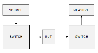 Figure 2: Multiple Test Points Figure 2: Multiple Test Points
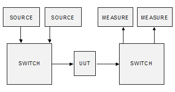 Figure 3: Multiple Instruments Figure 3: Multiple Instruments
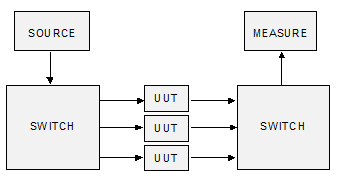 Figure 4: Multiple UUTs Figure 4: Multiple UUTs
Switch TypesWhen designing the switching portion of a given test system, it is important to define the configuration and implementation of the individual switches that connect the instrumentation to the unit under test (UUT). There are three terms used to describe switch configurations:
- Number of poles (e.g., single/double/triple pole)
The term "pole" refers to the number of common terminals contained within a given switch. Figure 5A shows a single-pole switch in the open position. The term "throw" refers to the number of positions in which the switch may be placed that create a signal path or connection. A complete description of Figure 5A is single-pole, single-throw, normally open (SPST-NO).
Figure 5B shows a single-pole, double-throw (SPDT) switch. One terminal is normally open (NO) and the other is normally closed (NC). The third terminal is the common terminal such that only one terminal can be connected, depending on the state of the switch. A complete description of Figure 5B is single-pole, double-throw (SPDT).
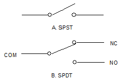 Figure 5: Single Pole Switch Figure 5: Single Pole Switch
Figure 6 shows a double-pole, double-throw (DPDT) switch. Both poles are actuated simultaneously when the relay is energized.
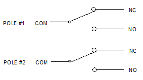 Figure 6: Double Pole Switch Figure 6: Double Pole Switch
The “form”, or “contact form”, is a term used by relay manufacturers to describe the contact configuration of a relay. “Form A” refers to a single-throw, normally open switch. “Form B” refers to a single-throw, normally closed switch, and “Form C” indicates a double-throw switch. An alternate designation for a double-throw switch is a Change Over (CO). Using this nomenclature scheme, virtually any contact configuration may be described.
Automated Test SystemsSimple semi-automated test systems have been designed in the past using the required instrumentation as part of a test fixture. This type of test system is normally designed to test a single module or circuit card. Any automation for this type of system uses the built-in capability of the instruments to run the required tests. The test results for these types of systems are manually recorded on a data sheet. The switching included in this type of system is manual and the test fixtures are usually built in-house.
As the need for testing increases or as test requirements become more complex, a computer controlled test system is usually the best choice. Advantages to automated test systems include:
- As operator intervention is less, there are fewer chances for test errors
- Test results are more often more accurate and more consistent
- Data can be more effectively analyzed since they are compiled into a database
- Complex calculations are possible
- Throughput of units under test is higher
When automating the test system, switching functions must also be automated. In systems where the signals are electrical, a programmable instrument called a scanner, matrix, programmable switch, multiplexer, or switching network is employed.
Designing Automated Test SystemsDesigning switching systems for an automated test system requires knowledge of the input/output signals to be switched and the test routine to perform the test. Automated test systems are usually designed with the flexibility to handle a variety of signals because test requirements change frequently.
The first step in designing a test system is to produce a Test Requirements Document (TRD), which outlines the system configuration and switching needs. Given that versatility is of utmost importance, designing the switching function may be one of the most difficult parts. To help design a switching system, one of the following switching topologies may be used, alone or in combinations. Figure 7 shows the basic topology.
 Figure 7: Switch Topology Block Diagram Figure 7: Switch Topology Block Diagram
Basic Switch TopologyThis basic switch topology connects one input to one output. It is generally used in control applications to:
- Connect a power supply or control signal to the UUT separate from other source-measure-interface circuitry
- Initiate an independent element of the system, for example, a device with non-electrical input or output, such as a motor or transducer
Marvin Test Solutions' GX6315 provides 3x15 independent single-pole, double-throw (SPDT) relays that may be used for power switching in the basic switch topology. The GX6338 provides 3x38 independent single-pole, single-throw (SPST) relays that may be used for low current switching in the basic switch topology. For more information about the SPDT and SPST configurations, refer to the section on “Switch Types”.
Multiplex or Scan TopologyThe multiplex or scan topology is used to connect one instrument to multiple UUTs or multiple instruments to a single UUT. The connections can be sequential (such as scan in Figure 8) or non-sequential (such as multiplex in Figure 9). In addition, multiplexing permits more than one simultaneous connection - for example, routing the UUT output to an AC voltmeter and to a frequency counter.
The 1:X configuration is sometimes used to connect a source to many points or a single point to many measure instruments. The X:1 configuration is used to connect several sources to a single point or many points to a single instrument. To synchronize source and measurement connections, a 1:X/X:1 pair can be switched together.
As shown in Figure 8, the scan topology is equivalent to a rotary selector switch. With this type of topology, there are two common versions:
- Make-Before-Break, which makes the new connection before breaking the existing connection
- Break-Before-Make, which breaks the existing connection before making the new connection
Either of these types can be implemented in a test system. Unless otherwise indicated, the non-shorting type is assumed.
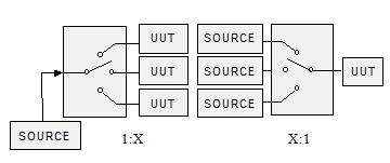 Figure 8: Scan Topology Figure 8: Scan Topology
Marvin Test Solutions' GX6264 is Multiplexer/Scanner that can be used for the scan topology. All products are of the Break-Before-Make version, although it is possible to switch multiple points simultaneously using different Scan Groups.
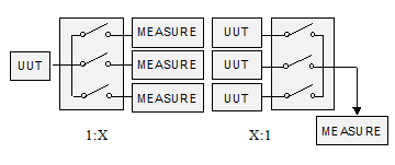 Figure 9: Multiplex Topology Diagram Figure 9: Multiplex Topology Diagram
Switch Matrix TopologyThe switch matrix topology connects multiple inputs to multiple outputs. With this configuration, multiple instruments are often connected to multiple points on a UUT. Though the switch matrix topology is the most complex, it certainly is the most versatile. Figure 10 illustrates the switch matrix topology in simple terms.
The switch matrix topology provides the most flexible switching method. However, the following issues must be addressed when using a switch matrix: stubs (unused relays) may generate electrical noise if the frequency is above 10 MHz. If you are using a switch matrix to switch high frequency signals, use the "cleaner" switch paths with shorter stubs. For example, the bottom-left switch shown in Figure 10 is the “cleanest” path since it has the shortest stubs. The top-right switch in the same figure is the “noisiest” path as it has the longest stubs.
The flexibility provided by the switch matrix means that any point could be connected to any other point. Extreme care should be taken when developing the control software to prevent shorts between low impedance sources (such as power supplies). A typical method to prevent such shorts is to use a resistor in series between the power supplies and the switch matrix if these signals are for measurement purposes only.
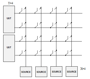 Figure 10: Switch Matrix Topology Diagram Figure 10: Switch Matrix Topology Diagram
Marvin Test Solutions' GX6616 is a true switch matrix that can be used when the switch matrix topology is selected. This product has 6 groups of 2x16 and offers multiple configurations from 2x96 to 6x16 (any of the 6 points may be connected to any of the 16 points).
Switching Instrument CriteriaEvery time a signal passes through a connecting cable or switch point, errors may be introduced. It is important to select the correct switching elements and proper topology carefully in order to maintain the integrity of the signal.
Newer switching elements come very close to the ideal switch. The ideal switch is:
- An open circuit (zero capacitance, infinite ohms) when open
- A short circuit when closed (zero ohms)
- Completely isolated from the other switches
- A discrete channel completely isolated from the others
All of these factors are critical in high accuracy and low level signal applications. In many systems, different types of switches must be included to balance the technical and economic limitations.
The following is a list of important factors when choosing a switching instrument:
- Cost of expansion/adding more boards
- Switching topologies available
- Minimum/maximum number of switch points
- Variety of switching elements available
- Electrical specifications
- Ability to upgrade as the system requirements change
Switching System TopologiesIn a typical Automated Test System one or all of the three switching topologies can exist: Switch, Scanner/Multiplexer, and/or a Switch Matrix. These various topologies with some additional specialized information are shown below. The various switching topologies can be combined to meet the requirements of the test system.
As illustrated in block diagram form, the basic switch topology connects one input to one output. This input can be one or more signal lines, connected through Form A, B, or C switching elements. One pole is required for each signal line, with all poles controlled together. Figure 11 shows an example using each switch topology.
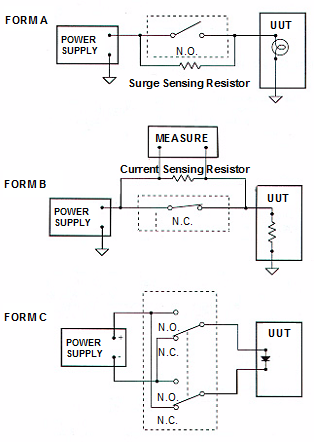 Figure 11: Basic Switch Topology (Form A, B, C) Figure 11: Basic Switch Topology (Form A, B, C)
Typical applications for this switch topology are power and control applications. Because each switch is independent and isolated, more than one switch can be closed at the same time.
Hardware that implements the basic switch topology often provides the flexibility to select Form A, B, or C switching and the number of poles controlled together. If the test system designer is willing to do external wiring, then any topology can be built from the basic switch topology.
The Marvin Test Solutions GX6315 can be used to perform all switching functions shown in Figure 11. As this product contains 45 individually controlled high current single-pole double-throw (SPDT) form C relays with a contact rating of 7A per channel it is an ideal candidate for power supply switching. The COM and NO poles of the relay will be used in the first example, the COM and NC poles will be used in the second, and two relays (COM, NO, and NC) will be used in the third.
Scanner/Multiplexer TopologiesMost scanner and multiplexer topologies connect one input to “n” outputs or “n” inputs to one output. These are the most commonly used topologies in signal switching for small systems. The simplest scanner is a Form C contact as shown in Figure 12A, switching a supply to either of two loads. Implementing this with two Form A contacts creates a simple multiplexer. The supply can now be connected to either one or both loads as seen in Figure 12B.
The major advantages of multiplexing over scanning are:
- Multiplexing permits an all-open state
- Multiplexing permits any order; scanning is sequential
- Multiplexing allows simultaneous connections; scanning does not
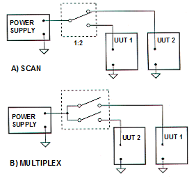 Figure 12: Basic Scanner Multiplexer Figure 12: Basic Scanner Multiplexer
The multiplexing method is the most used because it provides the most flexibility. In addition, sequencing of multiplex connections can be programmed in any order. Scanning is most often used in stand-alone systems without computer control. When designing a multiplex test system, the designer must consider the consequences of simultaneous connections in the system in case of software error or hardware failure (stuck relay). Various strategies can be used to handle this, from reconfiguring the switching or adding protection circuitry to adding software checks in the test program.
Multiplexing and scanning are used in a test system to connect one instrument to multiple UUTs or multiple instruments to one UUT. Sample configurations are shown in Figures 13 and 14. Figure 13 shows 2-pole multiplexing of high and low connections to the UUT. The same hardware can be used as both the 1:N and N:1 blocks. Figure 14 shows a ground-referenced system with 1-pole switching. Two additional multiplexers are used to connect the same instruments to a second UUT.
Marvin Test Solutions' GX6264, GX6315, and GX6338 may be used in the examples shown in Figures 12, 13 and 14. The GX6264 offers programmable configuration of differential (2 wire) and single-ended (one wire).
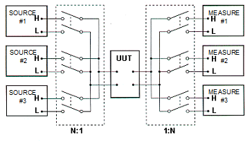 Figure 13: Two Pole Multiplexing Figure 13: Two Pole Multiplexing
For multiplexed switching, Form A SPST-NO contacts are used almost exclusively. One- and two-pole configurations are common, with more poles used in special situations (i.e. guarding).
Configurations equivalent to multiple pole configurations can be built from single-pole multiplexers controlled together. However, proper shielding, guarding, and noise cancellation are often more difficult. Control can also be synchronized to implement a 1:N/N:1 switched pair.
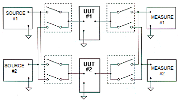 Figure 14: Switch Topology (Form A, B, C) Figure 14: Switch Topology (Form A, B, C)
Matrix TopologyThe matrix topology is used to connect any input to any output. Simultaneous connections are possible with one input driving many outputs or, less often, several inputs driving one output. The most common terminology to describe matrix size is by rows and columns. As shown in Figure 15, any row can be connected to any column by closure of the relay at the intersection or crosspoint of a row and column. The main advantage of a matrix switching system is the flexibility of the connections allowed. The matrix topology connects multiple instruments to multiple points on a UUT, or multiple instruments to multiple UUTs. Direct connections between source and measure instruments are also possible.
Figure 15 (exploded view) illustrates a crosspoint implementing a 3-pole, Form A, switching of high, low, and guard signals. This type of structure permits maximum flexibility when connecting instruments and the UUT to the matrix. When designing the matrix, the number of poles per crosspoint is related to how the instruments are connected to the matrix. Single-pole matrix switching is the most common type.
Marvin Test Solutions' GX6616 is true switch matrix that may be used in the examples shown in figures 15, 16 and 17. These products offer a single-ended configuration of up to 6 rows by 16 columns or 2 rows by 96 columns. In the differential (2-wire) configuration, these products may be used to switch 3 rows by 16 columns or 2 rows by 48 columns. Using several boards, these products may be used to create unlimited switch matrices.
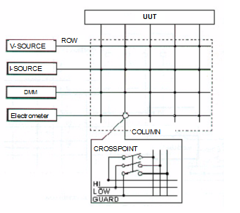 Figure 15: Matrix Topology Figure 15: Matrix Topology
In switching matrices, two connection methods can be used, as shown in Figure 16. The common ground system is used in high frequency systems where low impedance returns and coaxial cabling are required. The switched low configuration is used in low frequency or DC applications where floating measurements are required.
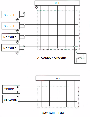 Figure 16: Single Pole Matrix Figure 16: Single Pole Matrix
Two-pole matrix switching is used for differential (balanced) systems or to create 4-wire measurements. An example is shown in Figure 17A where a digital multimeter (DMM) instrument makes a 4-wire measurement using two 2-pole rows of the matrix.
The 2-pole configuration can also used for guarded source or measure connections involving high impedance or low level signals as shown in Figure 17B. Since guarding isolates sensitive lines from adjacent circuitry, the construction and wiring of hardware for guarded systems differs from that used in a general-purpose 2-wire matrix.
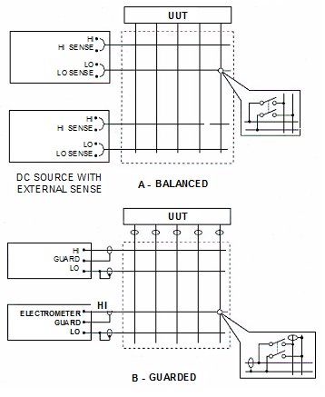 Figure 17: Two-Pole Matrix Figure 17: Two-Pole Matrix
For sensitive measuring applications, the 3-pole matrix switching method is useful. The 3-pole method isolates the high and low signals from the other signals. This is done by additional shielding which is not at circuit low or earth potential. The 3-pole configuration is also used for isolating source/measure signal pairs with a driven shield (guard).
Switching matrices may be used as building blocks for larger matrices by interconnecting them along the columns or rows. Matrix blocks can be connected to form a long narrow matrix. This is useful when a large number of instruments and UUT connections are required, but only a few signals are used for each test step.
As the following points illustrate, the matrix topology is the most efficient method because it offers:
- Reduced hardware and cost
- Straightforward programming
- Maximum switching flexibility via software control
- Maximum test flexibility to run different devices or different test programs
However, there are several of the drawbacks to matrix switching:
- Safety considerations as it is difficult to confine hazardous signals to certain paths
- Increased crosstalk between paths
- Shunt loading and impedance matching limits bandwidth
- Additional cost of switches for every possible signal path
- Lower reliability due to more switches and increased possibility of misconnection
Switching ElementsWhen a switch turns on, it behaves according to the characteristics and properties of the switching element. Therefore, any element chosen for use in a switching system should approach the ideal switch model.
Figure 18 illustrates the schematic representations of the four types of electrically controllable switching elements. Because of the advancement of relay designs, the relay family of switching elements offers the best overall performance at a reasonable cost.
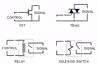 Figure 18: Switching Elements Figure 18: Switching Elements
Each of the four types shown above has advantages and disadvantages. For Automated Testing purposes however, the Relay offers the best performance. A FET switch is the fastest switch of the group, although it has a high ON resistance and the switchable signal level is typically limited. The Triac is a good solution for high current, high voltage switching but is rarely being used in ATE. The same holds true for the Solenoid Switch, although some applications require its use. Since the relay is the most common switching type used in ATE systems, the rest of this section will focus on types of relays and their advantages.
Types of RelaysOf the many types of relays, only a few are suitable for ATE applications. Among the more common types are electromechanical (armature) and dry reed. Table 1 compares some key parameters of these two relays.
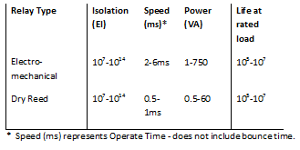 Table 1: Relay Comparison Typical Specifications Table 1: Relay Comparison Typical Specifications
Maximum Relay VoltageThe maximum voltage that a relay can reliably switch at is determined by:
- The gap (spacing) between the contacts
- The dielectric of the gas inside the relay
An arc will develop if the gap is too small between the two contacts. Arcing is common when switching high voltage, but if the relay has the proper gap, arcing is reduced.
In addition, the environment affects the degree of arcing. A humid or highly oxygenated environment promotes arcing and a dry climate reduces arcing. Open relays allow ambient air into the switching area while sealed relays contain a controlled internal environment from the relay manufacturer. Mechanical type relays are made as open or sealed units. Reed relays, by virtue of their construction, are always sealed.
When the voltage across the relay contacts exceeds the maximum switching voltage specified for the relay, arcing is usually present. An arc due to an AC signal is usually reduced as soon as the voltage level drops to zero.
Maximum Relay CurrentTypical relay specifications break down maximum current into maximum carry current and maximum switched current.
Carry current is defined as the current that can be passed by previously closed contacts. The cross-sectional area of the path from pin to pin through the switch limits carry current.
Switched current is the maximum current that can be interrupted by the relay. Contact plating and material are the primary factors in the switched current specification. If a high current is switched constantly across the contacts, the heat rises and arcing at the contacts degrades them at a rapid rate. In extreme cases, the contacts may “weld” together. If the specified life of the relay is to be attained, the power rating of the relay must also comply with the current and voltage values.
Maximum Relay PowerThe maximum power that a relay can switch relates to the temperature rise in relation to reasonable contact life. An over-power condition dramatically shortens relay life. Signal handling relays have their power rating specified in either volt-amps (VA) or watts. Relays that have their power rating given in watts are DC relays. If the relay is a DC type, the relay’s power must be used to rate the relay’s power handling capability.
AC type relays are designed to handle AC loads and are usually rated in volt-amps. When power is rated in VA, the power factor is not a consideration and volts switched times amperes switched or carried is the calculation used.
Contact PotentialEMF (Electromotive Force) is generated when two dissimilar metals come into contact. Because a relay contact is typically a plated alloy, even the two supposedly similar halves of the contact are not the same. There are differences due to alloy composition and the working of the metal as well as the thermal EMFs generated by the plating to the alloy junction.
In addition, EMF is generated when heat is conducted along the leads of the switch. The difference in the heat flow between the different leads causes a thermal EMF. A secondary source of thermal EMF is from winding inconsistencies and variations in coil wire diameter. In a reed relay, these radiate heat, which causes temperature variations in the switch.
In a test system, these thermal EMFs add a voltage error to the measurement system. Depending on the relay, this error may range from less than a microvolt to tens of millivolts. If the error is significant with respect to the sourced or measured reading, the thermal EMF must be known and compensated.
Relay Operating SpeedThe rate at which the contacts may be cycled for reliable operation is known as the operating speed. It is limited by the actuation and release times. Actuation time is measured from when power is applied to the coil until the contacts have settled. Release time is the opposite of actuation time. It is measured from the time power is removed from the coil until the contacts have settled again (including bounce).
An operating frequency, or repetition rate, lower than that allowed by the switching times is often specified for a relay. This is done to limit temperature rise and allow for contact settling. Of these two, temperature rise is more critical. When a relay is used near its power or voltage rating, the duty cycle must be adjusted to allow for cooling time. A lower operating frequency or altered duty cycle produces cooler temperatures.
Relay Contact Resistance Versus LifeContact resistance is the resistance across a closed set of contacts. This parameter is typically measured using a four-wire configuration with nominal voltage applied to the coil. Unless otherwise specified, a contact resistance specification is for new conditions.
For dry switches, the contact resistance is inversely related to the contact area. Electromechanical relays with large contacts have a lower contact resistance than a reed switch with relatively small contacts.
Life, or the number of operations for which a relay is expected to perform, is typically limited by mechanical operations and by the number of operations under a certain load until a specified resistance across closed contacts is reached. Without an end-of-life contact resistance specification, the life under load specification is meaningless. Dry switches typically have a life specified to a contact resistance less than 1 or 2 Ohms.
A relay may fail in one of several modes, including mechanical (actuation) failure and contact failure. A coil wire break, a glass seal fracture or reed fatigue in reed switches, or an armature mechanism failure in electromechanical relays can cause mechanical failure. A relay contact failure can occur when excessive heat or a high current or voltage pulse causes the contacts to weld. Oxidation, excessive charring and pitting, or insulating deposits on the contacts can cause an open circuit.
Because actual contact life is important, much effort has gone into finding and choosing “good” contact materials. Gold, silver, and palladium have traditionally been used for their good electrical conductivity and relatively low susceptibility to oxidation. Increasingly, rhodium and ruthenium are being plated over more traditional contact materials to increase the contact life. Rhodium’s structure is cubic, which is more stable than that of earlier contact plating. For even greater stability, the hexagonal structure of ruthenium is used.
Relay InductanceA relay coil also produces inductance because it is a coil of wire. As an inductor, the current in the coil cannot be changed instantaneously, since V=L(di/dt), without generating an excessive voltage spike. A diode is often used across the coil with the cathode at the positive voltage end of the coil. The suppression or “back” diode will conduct the coil current when the relay drive is removed. See Figure 19.
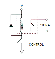 Figure 19: Suppression Diode Figure 19: Suppression Diode
Insulation ResistanceInsulation resistance (IR) is a measure of the resistance between two isolated pins on the relay. Available insulator materials provide a wide range of insulation resistance (105-1014 K Ohm) in various environments. The primary factor to limiting IR is bulk leakage and surface leakage. Bulk leakage is through an insulating material, usually after it has absorbed moisture from the environment. Surface leakage is across the surface of the material, usually due to contamination such as salts or flux and/or other chemicals from fingers. The properties of some insulators change with applied voltage, so it is important to evaluate IR at or above the expected operating voltage.
Relay CapacitanceAll the components of a relay have inherent capacitances that are determined by the materials and physical configuration of the relay.
The typical capacitance from switch contacts to the coil is 0.2 - 15 pF. This capacitance can couple noise or other signals from the contacts to the control lines, and vice versa. Noise can also be coupled to a different switch through its contact-coil capacitance if it is driven by the same coil supply. An electrostatic shield between the switch and the coil can reduce noise by as much as a factor of 110. In addition, there is also capacitance across open contacts. This type of capacitance depends on the contact area and the gap of the switch and is typically less than 2 pF. These inherent capacitances, due to physical characteristics of the relay, are one factor in limiting the frequency of the signal the relay switches.
Signal FrequencyTo obtain higher switching rates and good RF performance, specialized contacts and relay architectures are used. Operating frequencies greater than 50 MHz are possible with these types of relays. Inter-contact capacitance and contact circuit loss are factors that determine how well a relay is suited to high frequency applications. In addition, the design of the printed circuit board (PCB) also contributes to the selection of RF relays. Beveled etched signal paths and ground-guards are integrated into newer switch matrix PCB designs.
|