BackgroundThe application of MEMS technology has allowed Metal Oxide (MOX) Gas Sensors to be mass-produced at the wafer level with silicon wafer manufacturing offering cost reduction and scalability to large volumes. These gas sensor devices are suitable for precise measurement of Carbon Monoxide (CO) and a wide range of Volatile Organic Compounds (VOCs) such as Ethanol, Acetone and Toluene. Applications for these sensors, which are largely driven by health and safety considerations, include environmental monitoring, biological research, industrial control, portable breathalyzers and home air monitoring systems. The adoption of MEMS technology for MOX gas sensors has resulted in greatly reduced manufacturing costs. However, each of these sensors must also be tested, which presents a unique set of challenges when compared to the manufacturing and testing of typical semiconductor devices. This application note discusses how a semiconductor manufacturer of Gas Sensors employed a focused test solution that provided the required accuracy, accommodated very large site counts, and matched the over-all throughput performance of high performance semiconductor test systems at a much lower cost.
What is a MOX Gas Sensor?The MOX Gas Sensor is a MEMS device (Micro-Electro-Mechanical System) fabricated as a multi-chip module (MCM). The basic components of the MCM are the micro-controller ASIC, pre-tested on the wafer, and the sensor, the object of this test application. These components are placed on a common substrate and a lid is placed over the components with a small hole or mesh in the lid that allows gas into the sensor.
The sensor consists of a small heating element housed beneath a thin membrane coated with a proprietary metal-oxide material. The MOX material is a variable resistor that responds to chemicals in the gas it is exposed to. The MOX can be formulated to respond differently to certain types or classes of gas, called the target gas. In an environment of “clean” air, the MOX resistance can be several MOhms. When heated, and in the presence of the target gas, the resistance of the MOX material drops significantly, down to several tens of KOhms. When the application of heat is removed, and/or the test gas is eliminated, the MOX resistance returns to its previous value.
With the application of controlled heat, measuring the resistance of the MOX coating in the presence of clean air, and then measuring the resistance of the MOX coating in the presence of air with a controlled amount of the target gas (measured in Parts per Million), the ratio of the two measurements can be used to calibrate the device. In actual operation, the calibrated MOX resistance measurement is indicative of the density of the target gas in the environment.
Control of the sensor heater and MOX measurements, as well as device register read/write, are performed by the controller ASIC, which is in turn controlled by the test system over an I2C interface. The I2C interface is a four-wire bus consisting of the two-wire I2C bus (SCL and SDA), an interrupt signal and a reset signal. Figure 1 details the components that comprise the MOX Sensor MCM device.
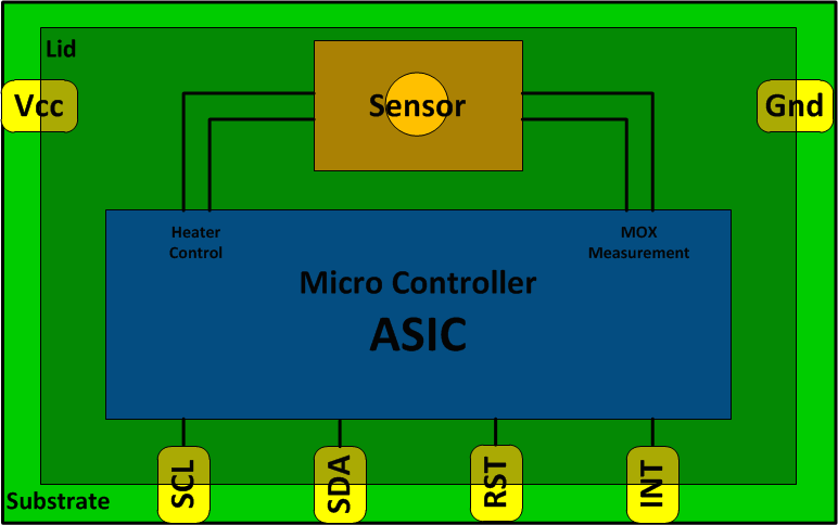 Figure 1: MOX Gas Sensor MCM Figure 1: MOX Gas Sensor MCM
Test System RequirementsTo test these devices, the test system needed to have the following capabilities and attributes:
- The time to test/calibrate a MOX sensor can be several tens of minutes. This long “dwell” time is required due to the need to “soak” the sensor(s) with clean air and the target gas. Clearly, using a large, high performance semiconductor tester, which is effectively sitting idle for many minutes during the gas soak time, is not a productive use of that expensive resource. The solution had to have a low initial capital cost.
- Test throughput is still important. With long dwell times, it was essential that the system support very large parallel test capability so the soak time can be amortized across many devices.
- The DUT load board had to reside in an enclosed environment where concentrations of gas could be precisely controlled. This precluded the typical practice of using handlers to load and unload devices, resulting in the requirement for manual insertion and removal of the devices. Consequently, a means for an operator to visually identify passing and failing components for manual binning was required.
- Once the desired soak time had been reached, all measurements needed to be completed in less than one second to avoid skewing of the results due to disparate soak times.
- As the component was a new design, the system needed to be expandable, so the test capacity could grow as production volumes increased.
- The devices arrive for package test after the wafer-level ASIC test is completed, with common I2C slave addresses for all devices. The system needed the ability to isolate the I2C bus to each device, eliminating the need to modify the slave address for testing. Since the load board involved manual insertion of the DUT, a test method was needed to verify correct component insertion prior to initiating the lengthy test process. A simple contact test achieved this, so the system needed to provide PMU/pin capability.
ImplementationArchitecture
The architecture selected was a hybrid PXI-based system consisting of a mixture of PXI instruments and external instruments controlled over USB. Note, the use of the word hybrid in this circumstance does not mean PXI Express hybrid – the PXI instruments are all standard PXI-1. In this context, hybrid means the combination of PXI and non-PXI instruments.
Power
The operating current of the device in normal, or idle, states was very low, but during measurements, experiments showed that, when the sensor heater was activated, inrush current per device could be quite high. To support a large multi-site configuration (up to 512 devices), PXI power solutions were deemed inadequate, so external Keysight E36313A power supplies were selected.
Digital Instrument
An obvious implementation is to use a dedicated digital instrument for each device being tested. This would meet the requirement to isolate the I2C bus for each device, but the cost for such a “brute force” approach would exceed the overall system budget. So a switched, or multiplexed, digital interface implementation was devised whereby each DUT would communicate over a dedicated I2C bus, minimizing the digital instrumentation resources. The instrument of choice, based on cost, channel density and ease of use, was the Marvin Test Solutions GX5295 digital I/O card.
With 32 channels per slot, per-pin PMU, deep pattern memory and a robust API function set, the GX5295 could test eight devices in parallel without slave address conflict issues. An 8:1 multiplexing scheme allowed one GX5295 to test 64 devices in groups of eight at a time, again avoiding slave address conflicts. This approach allowed one inexpensive GX5295 to measure a full 64-site load board in well under the allocated time budget. And, since the GX5295 supports synchronous multi-instrument expansion, the time to make measurements on 512 devices is the same as the time to measure 64.
|
|
System expansion is simply a matter of adding extra GX5295s, load boards, chambers and ITA cables, up to a maximum of 8 total (512 DUTs).
Load Board
Load board density was set to 64 devices (Figure 2). For reasons explained above, this provided a natural granularity for system expansion. To simplify the system/DUT interface, the mux switching devices were placed on the load board, eliminating external switching and the associated cables, while still maintaining good signal integrity.
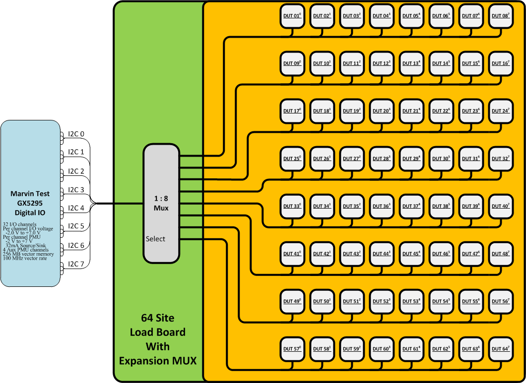 Figure 2: Load Board Figure 2: Load Board
The load board includes 64 tri-color LEDs for visually indicating Pass/Fail status of each DUT. The LED power includes a battery backup so the visual Pass/Fail state is retained even when the load board is removed from the system – which was necessary for the operator to manually remove and bin the devices. A charging circuit on the load board keeps the battery topped-off while tests are running.
Since the I2C interface is an open-collector bus, it requires external pull-up resistors for operation. These resistors interfere with the PMU contact test for determining proper DUT insertion in their sockets – the current through the pull-up resistors would swamp the ESD diode measurements. Consequently, a Vcc controlled pull-up relay was included to isolate the pull-up resistors from Vcc when making the contact measurements (Figure 3).
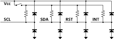 Figure 3: Pull-up Isolation Figure 3: Pull-up Isolation
Load Board Control
An inexpensive MTS GX5733 static digital I/O module was used to control all of the load board functions (I2C mux, tri-color LEDs and Vcc pull-up isolation relay). A special driver was developed that simplifies load board control.
PXI Chassis
The PXI chassis selected was the MTS GX7305 high-power chassis. The chassis provides 20 PXI-1 (non-express) slots – one for the MXI controller and 19 for instrumentation. The chassis exceeds the PXI minimum specifications for power delivery and cooling capacity, and includes functions for monitoring backplane voltages and slot temperatures.
Interface Test Adapter (ITA)
A dedicated ITA was designed for the GX7305’s hinged front panel, allowing for simple, clean cabling between the test system resources and the load boards. Cables from both the PXI instruments and the external E36313A power supplies mate to connectors on the back side of the ITA, which are hidden from view when the hinged panel is closed. Cables to the load board, Mass Flow Controllers and exhaust valves connect to the front of the ITA (Figure 4).
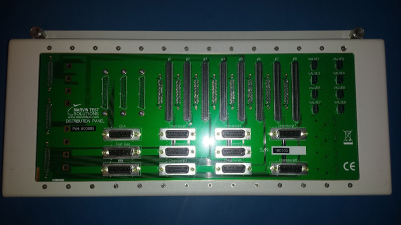 Figure 4: Interface Test Adapter Figure 4: Interface Test Adapter
Figure 5 details a block diagram of the test system’s resources and associated ITA.
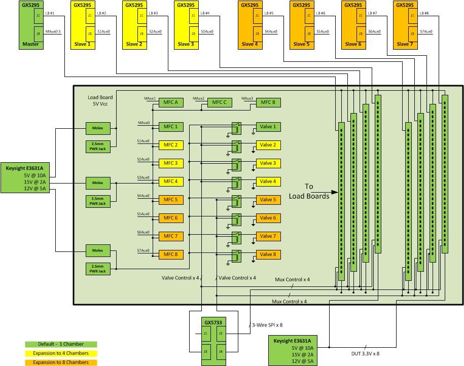 Figure 5: System Block Diagram Figure 5: System Block Diagram
Gas Control
To facilitate precise control of gas exposure to the DUT, an enclosed environment (chamber) was designed to house the load board and restrict the test gas to a confined space. The gas is introduced to the chamber via Mass Flow Controllers (MFCs) that meter Clean-Dry Air, Humidified Air and the Test Gas, allowing them to be mixed in precise quantities to achieve the desired gas densities (measured in Parts per Million). A separate MFC is also provided for each chamber to meter the mixed gas to the enclosed chamber in a controlled volume. Control of the MFCs is performed using the auxiliary PMU channels on the GX5295’s J3 connector.
Exhaust valves are used to evacuate the test gas from the load board chamber after the tests are complete. The exhaust valves are solenoid operated, powered by one of the E36313A power supplies, and controlled via 12 V switching relays located on the ITA.
Software
The software used to control the system is ATEasy®, v10. Software control was written to facilitate easy expansion of the system as well. ATEasy supports multi-threading applications. For each GX5295/load board/chamber, ATEasy instantiates a separate thread for processing measurements and generating data logging reports. The ATEasy test application queries the number of GX5295s installed in the system (one GX5295 for each 64-site load board), then dynamically allocates a thread for each. Processes common to all threads, such as initiating the digital test patterns that are run in parallel for each load board, are facilitated using thread synchronization.
Included in the ATEasy application are drivers for the GX5295s, GX5733, Keysight power supplies and GX7305 chassis monitoring, as well as an Excel spreadsheet driver for managing the data logging. There is a MOX driver, built on top of the GX5733 static digital instrument, for simplified control of the load board.
Included in the delivered package are tools for high-level creation of I2C bus patterns, concatenation and loading of I2C bus sequences, as well as downloading captured I2C bus traffic for diagnostics and analysis. Data logging to an Excel spreadsheet facilitates the use of all of the high-level data analysis tools of Excel, such as graphs, filters and application of formulas to the acquired measurements. |
|
Communication to the DUT is done over an I2C bus. As mentioned above, each device is preconfigured with an identical I2C slave address. Were all of the DUTs to reside on the same I2C bus, it would be necessary to reprogram each device with a unique slave address prior to testing to avoid bus conflicts, and then re-program the slave address to the default value for delivery to the customer. Using a dedicated bus per device allows all communication to occur using the default address, saving time and money, and avoiding potential human error. A single GX5295 with 32 I/O channels can communicate across eight I2C busses simultaneously without concern for address conflicts.
The I2C test patterns were generated using a simple utility written in ATEasy (Figure 6). Bus commands are constructed using a drop down menu of pre-defined bus commands for reading and writing to a device’s registers. An idle command is also available to allow insertion of dead-time between commands that require it, or to serve as a visual separation in the data patterns for debugging purposes.
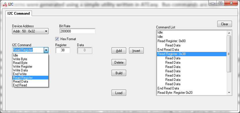 Figure 6 : I2C User Interface Utility Figure 6 : I2C User Interface Utility
Based on the requirements of the test processes, a sequence of commands are generated for a single device. Then using DIOEasy (Figure 7), a tool for generating and diagnosing GX5295 digital test patterns, the single (four-wire) bus control is copied to the remaining seven busses supported by the GX5295. Each test process is written as series of stand-alone pattern sequences so they can be concatenated together in any order desired.
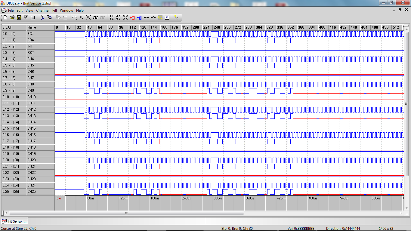 Figure 7 : I2C Pattern Editing using the DIOEasy Tool Figure 7 : I2C Pattern Editing using the DIOEasy Tool
An offline utility is included in the ATEasy application that performs this concatenation, generating one large test file that is quickly loaded to the test hardware during initialization of the system. To aid in debugging and diagnostics, a text file is generated identifying the order of the loaded tests, their initial vector address, and the pattern size of each pattern sequence.
Lock NVM, :Start 0, :Size 204, :Length 1632
Unlock NVM, :Start 2656, :Size 204, :Length 1632
Dut Poll, :Start 5312, :Size 207, :Length 1656
Dut Status, :Start 7992, :Size 207, :Length 1656
Start Sequence, :Start 10672, :Size 204, :Length 1632
Pre-Init 3, :Start 13328, :Size 240, :Length 1920
Pre-Init 5, :Start 16272, :Size 204, :Length 1632
Pre-Init 7, :Start 18928, :Size 204, :Length 1632
Pre-Init 12, :Start 21584, :Size 1908, :Length 15264
Pre-Init 14, :Start 37872, :Size 1363, :Length 10904
Pre-Init 16, :Start 49800, :Size 240, :Length 1920
The state of each pin is recorded during test execution. At the completion of the test, the actual bus traffic (commands and DUT responses) can be uploaded from the hardware to DIOEasy, allowing the user to evaluate and/or document I2C bus communication.
Test ProcessContinuity
The per-pin PMU function available with each GX5295 I/O channel is used to source a small current through each of the DUT’s ESD diodes, and the resulting voltage drop across the diodes is measured to determine if the DUT is correctly installed in its socket. Prior to doing this, the pull-up isolation relay needs to be enabled so current flow through the I2C pull-up resistors does not corrupt the continuity measurement. Devices are binned according to their pass/fail status. Future test evaluation is bypassed for any device having a “Failed” bin status.
Sensor Initialization
Prior to exposing the DUT to a test gas and measuring the MOX resistance, the sensor must be initialized. The Initialization reads relevant NVM (Non-Volatile Memory) data and stores it for future data correlation. It also dynamically calculates minimum and maximum permissible MOX resistance values for each DUT, based on the stored Heater Resistance and the current chamber temperature. These values are stored for future use. The Gas Test will use these values when determining good/bad devices.
Gas Measurement
The Gas Measurement test is the heart of the MOX Gas Sensor production test. Once initialized, all devices in all chambers are exposed to a controlled mixture of “Clean/Dry Air” (CDA), “Humidified Air” (running CDA through a bubbler - BBL) and the “Test Gas”. The gas mixtures are precisely controlled (in PPM) using programmable Mass Flow Controllers. Each of the three MFCs is controlled by the application of 0 V – 5 V, representing 0% to 100% of the rated flow, respectively. A fourth MFC is included for each chamber/load board. The MFC control voltages are provided by the auxiliary PMU channels on the J3 connector of the GX5295s.
During the Gas Test, the concentration of the test gas, and the exposure time for each specific concentration, is defined by a “Soak List”. The soak list contains set points for the three gasses, and the duration to hold that concentration before moving to the next set point in the list. At the end of the defined time period, a MOX measurement is taken, compared against the MOX min/max values previously calculated, and recorded. Binning is set accordingly.
To simplify the application of the soak parameters, a form (Figure 8) was created in ATEasy that allows an engineer to create the soak list using a GUI. Set points can be added, inserted, modified and deleted. During execution, the GUI highlights where in the list the test process is, providing the operator an indication of how long the test has run, and how long until completion.
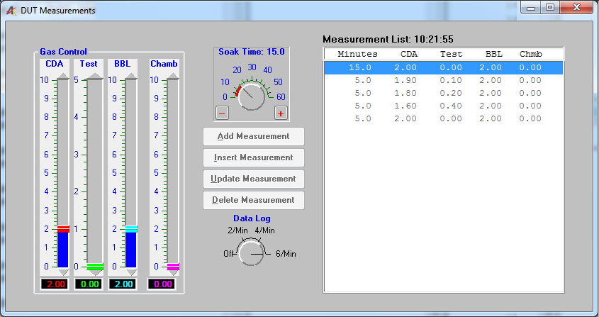 Figure 8 : GUI Soak List Figure 8 : GUI Soak List
An optional parameter that can be enabled when running the soak list is to make intermediate MOX measurements – measurements between the soak list set points. This provides additional characterization data of the MOX operation by logging additional measurements during the lengthy test process. The options for data logging are “Off”, measurements only at the set points, and “2”, “4”, “6” measurements/minute. Intermediate measurements are saved to the Excel data log file, but are not used in evaluation of pass/fail status.
Pre-Initialization
The devices arrive from the contract manufacturer (CM) with some information already stored in the device’s Non-Volatile Memory (NVM), such as the Product ID, a correlation Tracking Number, Heater Resistance and the ambient temperature the resistance was measured at, Slave Address, etc. The pre-initialization test allows an engineer to overwrite the NVM with new data. This is not a normal test process used during production. Instead, it is used to allow an engineer to run characterization tests on the device with complete control over all DUT parameters.
Sensor Aging
The Sensor Aging test is also not part of the normal production test. It is used to characterize the MOX under simulated aging processes. The aging test runs CDA to the part with an extended heater temperature, for a user-defined number of one minute cycles. Analysis data is collected during this process, and at the conclusion of the aging test, a normal Gas Test is run and the MOX characteristics recorded.
DUT Polling
When running the Gas Test, the Sensor Aging test, and other test processes, the DUT is programmed with a test sequence table with the processes executed and controlled by the micro controller. During this sequence table execution, the DUT registers are not available for access, except for a polling register. The polling register is updated during the table sequence execution and can be queried by the test system to determine if the sequence table is done, or if the current table in the sequence is executing. Since polling is required for several of the MOX tests (every process that utilizes sequence tables), it is implemented as a subroutine that can be called when needed. The time that it takes to execute the sequence table can vary depending on the test requirement – number of steps in the table and delay parameters per step. To provide the operator with status of the sequence execution, an Elapsed Time form (Figure 9) was created to provide visual feedback of the time remaining to complete the sequence table.
 Figure 9 : Elapsed Time Form Figure 9 : Elapsed Time Form
DUT Status
Like DUT Polling, the DUT Status is queried by multiple test processes, and is implemented as a subroutine. The status indicates the health of the DUT – specifically, if a Power On Reset has occurred recently. The POR bit is set whenever power to the device is interrupted, or if a Reset is initiated. Reading the POR state resets the bit. Many of the tests will not function correctly, or are considered invalid, if a POR is indicated.
Chamber Characterization
One of the most challenging aspects associated with proving the efficacy of the test system, was characterizing the distribution of the test gasses in the chamber (Figure 10). The initial concept was to introduce the gasses at the four corners of the load board, assuming that, over time, the gas would mix and be distributed evenly within the chamber. But tests proved that the gas would not reach a homogenous concentration within the chamber in the time limit defined by the soak list. Increasing the flow rate of the test gasses, and extending the soak time, were both considered as a remedy for this shortcoming, but in the end were deemed too expensive in gas utilization and test throughput, respectively.
Extensive experimentation, later substantiated by fluid modeling, demonstrated that a modified manifold approach produced near ideal gas distribution. The gas was introduced at four points into a low-volume manifold located directly above the DUT sockets. Pin-holes in the manifold above each socket deliver a concentrated stream of the test gasses directly to each device. The end result was near optimal performance utilizing a minimum amount of test gas, without adversely affecting test throughput. The chamber design will be modified to incorporate these findings into the production systems.
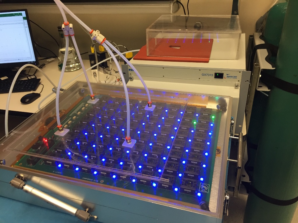 Figure 10 : Device Gas Manifold Figure 10 : Device Gas Manifold
SummaryIn conclusion, each of the criteria for the test system was met, or exceeded.- The solution had to have a low initial capital cost. Based on the PXI form factor, a creative hardware and software implementation resulted in a capital cost at well under 1/5 of the cost of a conventional semiconductor test system.
- The system needed to support very large parallel test capability. Site count can be expanded from 64 sites to 512 sites, in 64 site increments. At these capacities, a 35 minute test cycle still results in a throughput rating of just over 4 seconds per device. Further optimization of the test code, gas flow rate, soak times and pass/fail parameter optimization will drive the test time per device even lower.
- A means for an operator to visually identify and manually bin passing and failing components was required. Test status LEDs with battery backup provides the operator with a visual indication of DUT site pass/fail (Figure 11).
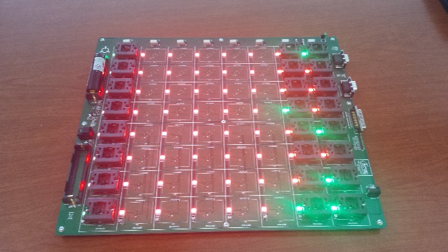 Figure 11 : DUT Board with LED Indicators for Pass/Fail Status Figure 11 : DUT Board with LED Indicators for Pass/Fail Status
- All measurements needed to be completed in less than one second. The time to measure the MOX resistance for 64 sites was measured at less than 800 mS. Due to the parallel operation of the GX5295 digital test instrument, extending the site count to 512 will not appreciably increase the measurement time.
- The system needed to be expandable. Site count can be expanded from 64 sites to 512 sites in 64 site increments.
- Isolate the I2C bus to each device. Each DUT socket has an isolated I2C bus for programming and reading/writing register, accessed as an 8 x 8 matrix (8 groups of 8 DUT’s).
- Provide PMU/pin capability. The GX5295 architecture comes standard with a PMU per pin capability, plus four additional PMUs for general purpose use. The PMUs provided an easy method to perform a contact test and the additional PMUs were dedicated to MFC control, helping to lower the system cost by eliminating extra hardware.
The specialized requirements associated with the testing of MOX gas sensors presented unique challenges. In particular, the large test “dwell” time required by these devices demanded a different kind of test solution – one that could be easily scaled to support very large parallel test capabilities with test assets that were significantly lower in cost than the traditional “big iron” ATE solution. As detailed above, a PXI-based solution based on off-the-shelf hardware and software provided the optimal solution – achieving both high throughput and very moderate cost.
|